Porting OpenWrt to Broadcom BCM6338 with 8MB RAM (D-Link DSL-2500U D3)
Part 1: Bypassing Locked CFE, Bare-Metal SPI MMIO Driver, and Network Stack Bring-Up
Author: Herman Semenoff (@GermanAizek)
Date: November 2026
Language: English | Русский | 中文 (简体)
| ← Back to Blog | Main Page |
1. Introduction & Mission Objective
In the embedded engineering and security research community, networking gear based on the Broadcom BCM63xx SoC family (MIPS32 architecture) is widely considered obsolete. One classic example of this era is the D-Link DSL-2500U (Hardware Revision D3) ADSL2+ modem/router.
Most mainstream distributions (including upstream OpenWrt) have abandoned these legacy platforms: official BCM6338 target support was phased out, modern build images exceed the flash capacity by 200–300%, and an 8-megabyte system RAM budget is universally deemed insufficient even to uncompress a minimal Linux kernel.
Yet, from a low-level systems perspective, this device presents an exceptional target for reverse engineering, bare-metal hardware hacking, and kernel driver development. Our objective: breathe new life into the hardware by defeating vendor bootloader lockouts, resolving MIPS Data Bus Errors via custom memory-mapped SPI drivers, fixing dormant Ethernet PHY hardware, and establishing an ultra-stable, interactive OpenWrt environment accessible via serial console and network Telnet.
Target Hardware Specifications:
- SoC: Broadcom BCM6338 (MIPS32 4KEc V0.2 / V1.0 @ 240 MHz)
- RAM: 8 MB SDRAM (16-bit wide bus, total physical size 8,388,608 bytes)
- Flash: 2 MB SPI NOR Flash (Atmel AT26DF161, Device ID
0x1f46) - Ethernet: 1x 10/100 Mbps (integrated on-die EPHY transceiver)
- Bootloader: Broadcom CFE v1.0.37-8.7 (Build Date Dec 18 2009)
- Stock Firmware: D-Link RU_1.58 (Linux 2.6.8.4-mips-broadcom)
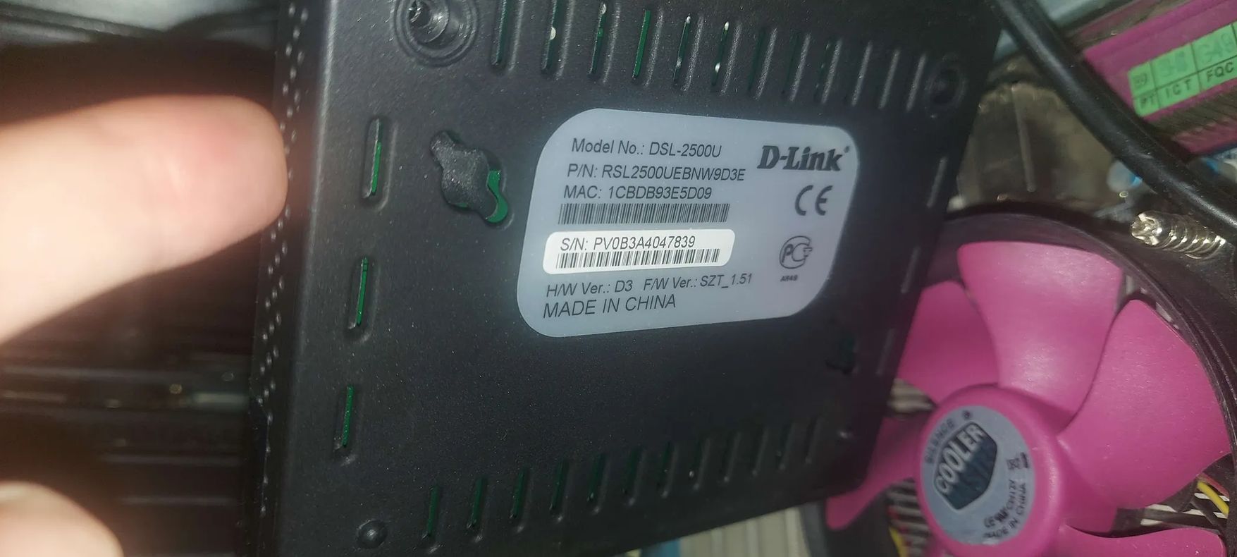
Factory label of the device: Model DSL-2500U, Hardware Revision H/W Ver: D3, MAC: 1CBDB93E5D09, F/W Ver: SZT_1.51.
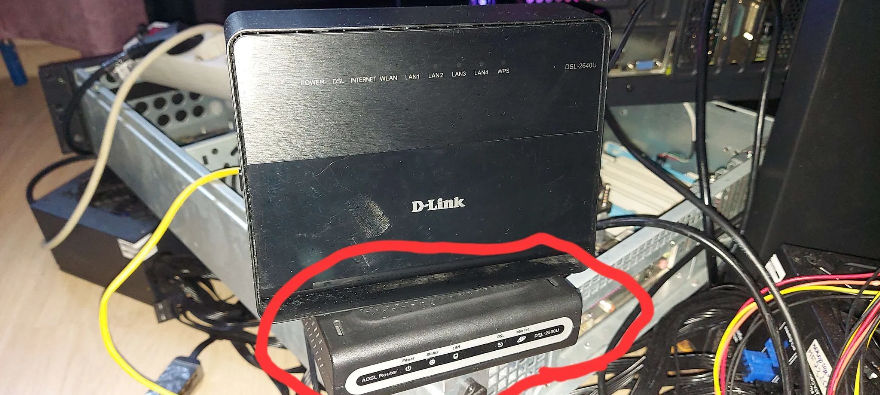
The target D-Link DSL-2500U D3 on our lab testbench (highlighted in red).
2. Analyzing Vendor Defenses & The CFE Recovery Traps
Our initial reconnaissance encountered multiple layers of vendor hardening:
Trap 1: Hardware Reset Button Disabled in CFE ROM
In standard Broadcom reference platforms, triggering CFE Crash / Recovery Mode is achieved by holding the physical Reset button during power-on. The bootloader spins up Ethernet, configures 192.168.1.1, and serves an HTTP recovery page on port 80.
On the DSL-2500U D3, however, holding Reset had zero effect: the power LED remained red, Ethernet stayed uninitialized, and no recovery server answered.
Disassembling the CFE binary dump revealed why: D-Link firmware engineers completely omitted GPIO Reset polling from the CFE ROM startup sequence. The Reset button is only sampled in userspace by the scfgmgr daemon inside the running stock Linux OS to trigger NVRAM defaults.
Trap 2: Out-Of-Memory Crash in Stock Web Server (Fatal error)
Attempting to flash custom firmware via the stock web interface (Management -> Update Firmware -> upload.cgi) resulted in immediate socket termination and the error message:
Fatal error during image uploading.
Static analysis of the stock micro_httpd binary and runtime memory inspection revealed the root cause:
- Of the 8 MB total physical RAM, the stock Linux 2.6.8.4 kernel and running background daemons (
cfm,snmpd,httpd,dhcpd,pvc2684d) leave merely ~536 KB of free memory. - When parsing the multipart upload in
upload.cgi, the server attempts to allocate a contiguous in-memory buffer (tmpfs /var) for the incoming 1.8 MB binary. - Once payload ingestion crosses ~600 KB, the Linux OOM Killer is triggered, killing
httpd. The HTTP connection drops with error codemsg[4]. Flashing any image larger than 500 KB through the stock web GUI is physically impossible on 8 MB RAM.
Trap 3: Strict checkFlashImage Validator & Root-First Layout
Broadcom stock validation logic in Busybox requires: \(ext{rootfsAddress} < ext{kernelAddress}\)
Standard modern OpenWrt images follow a Kernel-First layout. Uploading an image with kernelAddress < rootfsAddress triggers Illegal image validation rejection. We had to enforce a strict Broadcom Tag v6 structure, mapping SquashFS to offset 0xBFC10100 and the Linux kernel to 0xBFC72100.
3. Hardware Interfacing: UART Tapping & CFE Interception
Physical access via the serial UART interface became the only reliable attack vector.
UART Pinout (JP2 Header):
Near the power inductor and filter capacitors on the DSL-2500U D3 PCB lies a 5-pin service header labeled JP2:
| JP2 Pin on Router | Router Signal | Direction | Wire Color | USB-UART Adapter Pin | Description & Function |
|---|---|---|---|---|---|
Pin 1 (leftmost, above JP2 label) |
RX | Router Input | 🟨 Yellow | TXD | Receives spaces and commands from PC to intercept CFE |
| Pin 2 | NC | — | — | Not Connected | Unpopulated slot (unused) |
| Pin 3 | NC | — | — | Not Connected | Unpopulated slot (unused) |
| Pin 4 (penultimate) | GND | Ground | 🟫 Brown | GND | Common signal reference ground |
| Pin 5 (rightmost) | TX | Router Output | 🟧 Orange | RXD | Streams boot diagnostics and CFE prompt to PC |
| — | VCC (+3.3V) | Power | 🟥 Red | Not Connected | ⚠️ MUST REMAIN FLOATING! Kept isolated in the air |
[!WARNING] Critical Power Warning: The router must be powered solely via its dedicated 12V DC power supply. Never connect the 3.3V or 5V VCC lead from the USB-to-UART adapter to the router board — this would cause regulator backfeeding and destroy onboard switching converters and ICs. The red power wire must remain completely disconnected and floating.
Terminal Parameters: 115200 baud, 8 data bits, no parity, 1 stop bit (115200 8N1).
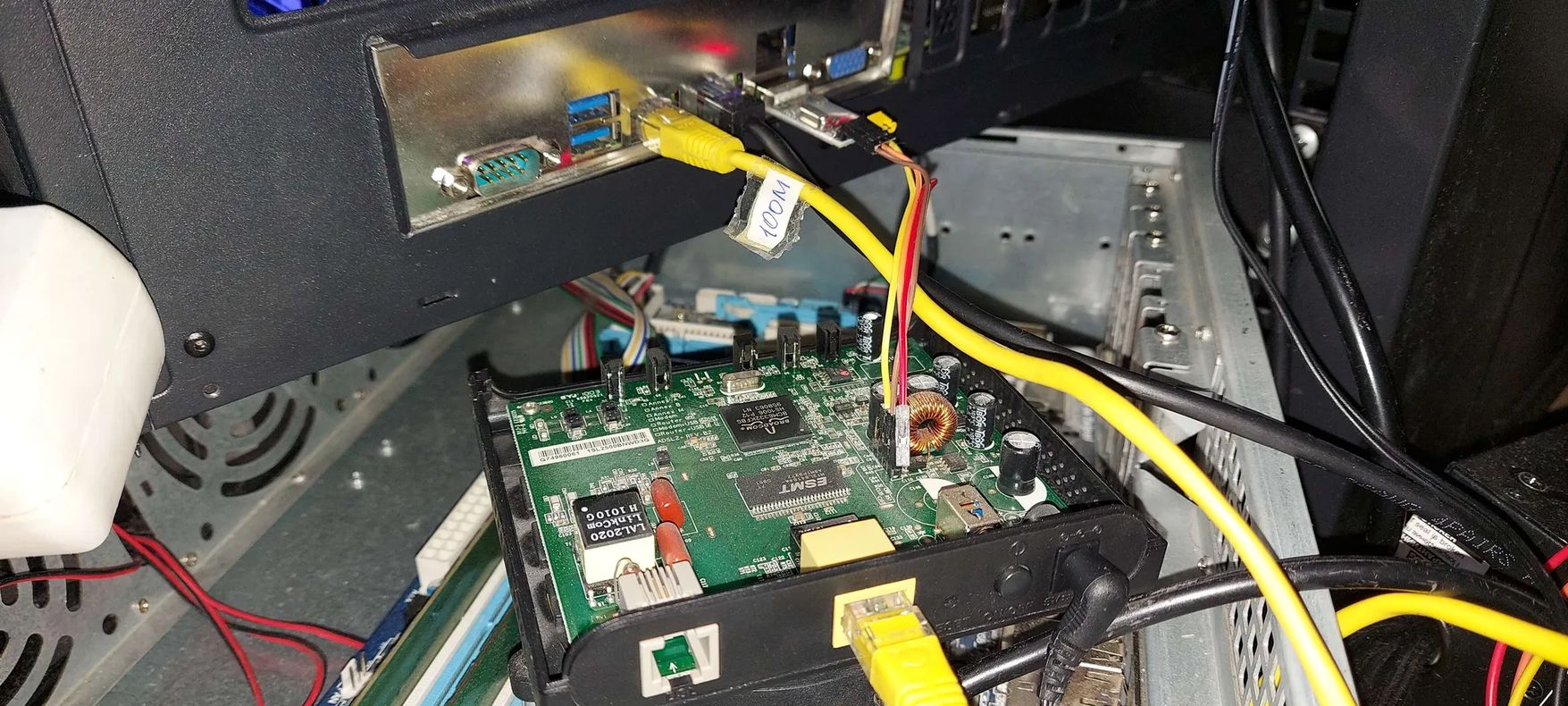
Overall hardware testbench setup: disassembled DSL-2500U board, direct host Ethernet connection ("100M" label), and serial UART jumpers wired to the workstation USB port.
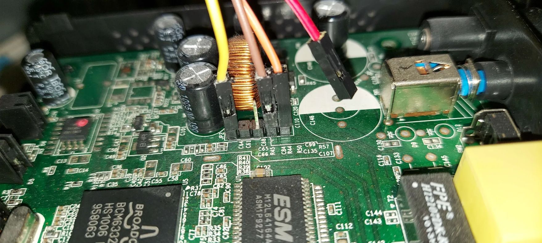
Macro view of the PCB: Broadcom SoC (marked BCM6332 / HS1006 / 958063), 8 MB ESMT SDRAM (M12L64164A), Atmel SPI Flash, and JP2 service header wiring: yellow wire (Pin 1, RX), brown wire (Pin 4, GND), orange wire (Pin 5, TX). The red 3.3V VCC wire is kept isolated and floating.
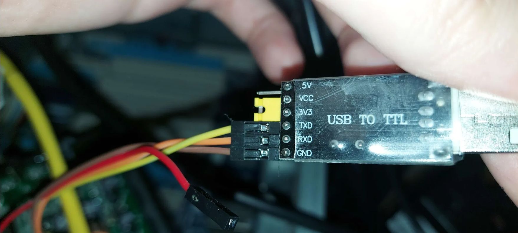
USB-to-TTL UART adapter configuration: logic level jumper bridging VCC and 3V3 (3.3V TTL mode). Connected lines: TXD (yellow wire), RXD (orange wire), and GND (brown wire). Red VCC wire is safely disconnected.
Catching the 1-Second CFE Auto-Run Window:
On power-on, CFE prints startup diagnostics and allows a strict 1-second delay for user interruption:
*** Press any key to stop auto run (1 seconds) ***
Auto run second count down: 1
Manual keystrokes over USB-UART often miss this window due to OS buffering. To guarantee reliable interception, we created a Python automation tool (cfe_auto_flash_and_boot.py) that monitors the tty device and injects space characters b" " every 25 milliseconds:
# cfe_auto_flash_and_boot.py excerpt
while not in_cfe:
    now = time.time()
    if now - last_spam >= 0.025:
        os.write(fd, b" ")
        last_spam = now
    r, _, _ = select.select([fd], [], [], 0.005)
    if r:
        chunk = os.read(fd, 2048)
        if b"CFE>" in chunk:
            in_cfe = True
            break
Once interrupted, CFE drops to the prompt and exposes its built-in HTTP recovery server on socket 0:
CFE> web info: Waiting for connection on socket 0.
In this mode, all 8 MB of SDRAM is entirely available. Firmware delivery succeeds over eth1 (192.168.1.2 $ o$ 192.168.1.1):
curl -s --http0.9 -F "filename=@openwrt_image.bin" http://192.168.1.1/upload.cgi
CFE ingests the full 1.83 MB image into memory without OOM and programs the SPI flash sector by sector.
4. The MIPS Data Bus Error (DBE) & Reverse Engineering Hardware SPI MMIO
With the first OpenWrt Backfire image (10.03.1, Linux 2.6.32.27) flashed, CFE uncompressed the kernel:
Code Address: 0x80010000, Entry Address: 0x80010000
Decompression OK!
Starting program at 0x80010000
The kernel initialized the MIPS core, allocated memory pools, registered MTD partitions, and proceeded to mount rootfs /dev/mtdblock2 (SquashFS). Then came the crash:
CPU 0 Unable to handle kernel paging request at virtual address 0xbfc10000, epc == 801709ec
Data bus error, epc == 801709ec, ra == 80160a28
Oops in fault.c:do_page_fault, line 178:
$ 0   : 00000000 10008401 00000000 00000000
$ 4   : 80456000 bfc10000 00000200 00000000
Call Trace:
[<801709ec>] my_read+0x44/0x88
[<80160a28>] bcm963xx_mtd_read+0x60/0x94
[<80145df0>] part_read+0x64/0xb0
[<80144d28>] mtd_read+0x78/0xbc
[<8014c274>] mtdblock_readsect+0x44/0x100
Kernel panic - not syncing: Fatal exception
Root Cause Analysis:
The Linux page fault and bus error handler arch/mips/mm/fault.c:do_page_fault trapped the panic. The kernel MTD stack trace traces the execution flow: sector read mtdblock_readsect in drivers/mtd/mtdblock.c delegates to partition handling part_read in drivers/mtd/mtdpart.c, routing through include/linux/mtd/mtd.h into my_read.
The function my_read in OpenWrt’s legacy bcm963xx_flash.c was designed for older Broadcom SoCs with Parallel NOR flash:
static int my_read(struct mtd_info *mtd, loff_t from, size_t len, size_t *retlen, u_char *buf) {
    memcpy(buf, (void *)(0xbfc00000 + from), len);
    *retlen = len;
    return 0;
}
On the BCM6338 with SPI Flash, address 0xbfc00000 (physical KSEG1 0x1fc00000) is only a 64 KB boot shadow window dedicated to initial CFE execution!
Any uncached read beyond 0x10000 (from >= 0xbfc10000) accesses an unmapped internal bus segment. The Broadcom internal interconnect fails to receive an acknowledgment and asserts a hardware MIPS Data Bus Error (DBE) exception.
The Solution: Writing a Bare-Metal SPI MMIO Driver in MIPS Assembly
To read arbitrary offsets from the Atmel AT26DF161 SPI Flash chip, the kernel must issue standard SPI Read commands (0x03) through the BCM6338 hardware SPI controller mapped at physical base address 0xfffe0c00.
BCM6338 SPI Controller Register Map:
| Offset | Register Name | Description |
|---|---|---|
0x00 |
SPI_CMD |
Command register (trigger transaction, assert CS0) |
0x02 |
SPI_INT_STATUS |
Interrupt status / transaction complete flag (bit 0) |
0x40 |
SPI_MSG_CTL |
Message control (Tx/Rx transfer length) |
0x41 |
SPI_MSG_DATA |
Transmit FIFO buffer (command + 24-bit address) |
0x80 |
SPI_RX_DATA |
Receive FIFO buffer (data read back from Flash) |
We wrote an independent MIPS32 assembly driver (patch_spi_mtd_v4.S) to replace my_read:
# patch_spi_mtd_v4.S - BCM6338 Bare-Metal Hardware SPI Driver
# Calling Convention (MIPS O32 ABI):
# a0 = mtd_info, a1 = from (flash ofs), a2 = len, a3 = retlen, sp[16] = dest_buf

.set noreorder
.globl my_read_spi

my_read_spi:
    addiu   $sp, $sp, -48
    sw      $ra, 40($sp)
    sw      $s0, 36($sp)
    sw      $s1, 32($sp)
    sw      $s2, 28($sp)
    sw      $s3, 24($sp)
    sw      $s4, 20($sp)

    lw      $s0, 64($sp)            # $s0 = dest_buf
    move    $s1, $a1                # $s1 = flash_offset
    move    $s2, $a2                # $s2 = remaining_bytes
    sw      $a2, 0($a3)             # *retlen = len
    li      $s3, 0xfffe0c00         # $s3 = BCM6338 SPI MMIO Base

chunk_loop:
    blez    $s2, read_done
    nop

    # Cap single chunk to FIFO capacity (60 bytes)
    li      $s4, 60
    sltu    $v0, $s2, $s4
    beqz    $v0, do_transfer
    nop
    move    $s4, $s2

do_transfer:
    # 1. Clear interrupt status (write 1 to bit 0)
    li      $v0, 1
    sh      $v0, 0x02($s3)

    # 2. Prepare SPI Read Command (0x03) + 24-bit address
    li      $t0, 0x03
    sb      $t0, 0x41($s3)          # CMD: 0x03
    srl     $t1, $s1, 16
    sb      $t1, 0x42($s3)          # Addr [23:16]
    srl     $t1, $s1, 8
    sb      $t1, 0x43($s3)          # Addr [15:8]
    sb      $s1, 0x44($s3)          # Addr [7:0]

    # 3. Configure message length: 4-byte header + N payload bytes
    addiu   $t2, $s4, 4
    sll     $t2, $t2, 8
    sh      $t2, 0x40($s3)          # SPI_MSG_CTL

    # 4. Trigger transfer (assert CS0 + set Start bit)
    li      $t3, 0x0300
    sh      $t3, 0x00($s3)          # SPI_CMD: CS0 + Start

wait_ready:
    lhu     $v0, 0x02($s3)
    andi    $v0, $v0, 1
    beqz    $v0, wait_ready
    nop

    # 5. Extract received data from SPI_RX_DATA (offset +4 past header)
    li      $t4, 0
copy_bytes:
    addu    $t5, $s3, $t4
    lbu     $t6, 0x84($t5)          # Read RX FIFO
    sb      $t6, 0($s0)             # Store in kernel RAM buffer
    addiu   $s0, $s0, 1
    addiu   $t4, $t4, 1
    bne     $t4, $s4, copy_bytes
    nop

    # Advance offsets
    addu    $s1, $s1, $s4
    subu    $s2, $s2, $s4
    b       chunk_loop
    nop

read_done:
    lw      $s4, 20($sp)
    lw      $s3, 24($sp)
    lw      $s2, 28($sp)
    lw      $s1, 32($sp)
    lw      $s0, 36($sp)
    lw      $ra, 40($sp)
    addiu   $sp, $sp, 48
    jr      $ra
    move    $v0, $zero
We assembled and injected this binary routine into a kernel code cave at file offset 0x160920, while NOPing out the faulty KSEG1 loop at 0x173aa8.
Result: The kernel successfully validated the CFE1CFE1 signature, registered all 5 MTD partitions, and mounted SquashFS /dev/mtdblock2 with zero DBE faults.
5. Resurrecting the Ethernet Transceiver (Integrated EPHY)
With storage access operational, the system booted to a login prompt, but Ethernet remained non-functional:
ifconfig eth0displayed IP192.168.1.1- The kernel reported:
eth0: link forced UP - 100/full - flow control off/off - Host pings produced
Destination Host Unreachable - Hardware interface counters remained at
RX packets: 0(no ingress packets reached the MAC).
Investigating the bcm63xx_enet Driver:
Diving into the Broadcom Ethernet kernel subsystem (arch/mips/bcm63xx/boards/board_bcm963xx.c and drivers/net/bcm63xx_enet.c) exposed a fundamental discrepancy.
In the reference profile board_96338gw (board_bcm963xx.c:39), against which the kernel was built, Ethernet was configured as:
static struct board_info __initdata board_96338gw = {
    .name = "96338GW",
    .expected_cpu_id = 0x6338,
    .has_enet0 = 1,
    .enet0 = {
        .force_speed_100 = 1,
        .force_duplex_full = 1,
        /* has_phy = 0 */
        /* use_internal_phy = 0 */
    },
};
The network driver processed these flags as follows:
- In the platform device registration (
arch/mips/bcm63xx/dev-enet.c:144), when!pd->use_internal_phy, the kernel leavesdpd->phy_id = 0and omits the internal PHY interrupt lineIRQ_ENET_PHY. - In function
bcm_enet_probe(drivers/net/bcm63xx_enet.c:1708):if (priv->mac_id == 0 && priv->has_phy && !priv->use_external_mii) { /* using internal PHY, enable clock */ priv->phy_clk = clk_get(&pdev->dev, "ephy"); clk_enable(priv->phy_clk); }Because
has_phy == 0, the kernel never enabled the internal EPHY clock! The physical PHY silicon was unpowered and inert, despite the driver reporting a synthetic software “forced UP” status. Board and platform definitions are declared inboard_bcm963xx.handbcm63xx_dev_enet.h.
Binary Kernel Patch:
Locating the board table at offset 0x2a6794 in vmlinux.bin, we flipped the configuration fields:
enet0.has_phy(+0x20):0x00000000$ o$0x00000001enet0.use_internal_phy(+0x24):0x00000000$ o$0x00000001enet0.force_speed_100(+0x40):0x00000001$ o$0x00000000enet0.force_duplex_full(+0x44):0x00000001$ o$0x00000000
Boot Verification:
Upon flashing the patched kernel, the boot log confirmed real hardware initialization:
bcm63xx_enet MII bus: probed
bcm63xx_enet bcm63xx_enet.0: attached PHY at address 1 [Broadcom BCM63XX (1)]
eth0: link UP - 100/full - flow control off
The MDIO bus detected the on-die PHY, and a genuine physical 100M Full-Duplex link was established.
6. The 8MB RAM Barrier: Eliminating OOM & Scheduler Livelocks
With physical connectivity resolved, the final hurdle was extreme memory starvation and scheduler livelocks.
Dumping kernel memory statistics via SysRq-m revealed severe pressure:
SysRq : Show Memory
Normal free:512kB min:360kB low:448kB high:540kB
slab_unreclaimable:1652kB
active_anon:504kB inactive_anon:656kB
Of the 5.1 MB available to the kernel, unreclaimable slabs (descriptors, conntrack tables, iptables rules) consumed 1.65 MB, leaving barely 500 KB for userspace.
The kernel watermark min_free_kbytes was set to 360 KB. Whenever allocations pushed free memory below this threshold, the zone allocator entered direct page reclaim (shrink_zone).
Crucially:
- The system has no swap space;
- RootFS is read-only SquashFS;
- User processes (
ash,init,uci) reside in anonymous pages that cannot be reclaimed without swap!
The allocator hung in congestion_wait, pushing tasks into unrecoverable D (Uninterruptible Sleep) states.
Exacerbating this was hotplug2: on every network interface or tty event, it forked /sbin/hotplug-call, which in turn invoked /sbin/uci up to 10 times. This fork storm in sub-300 KB conditions triggered rapid OOM crashes.
Systematic Optimization:
- Pruning Heavy Kernel Modules: Removed
nf_conntrack,iptable_*,ppp*, andusbfrom/etc/modules.d/. This reclaimed >1.2 MB of slab RAM. - Disabling Hotplug Daemon: Deactivated
hotplug2and purged event handlers in/etc/hotplug.d/. The static hardware layout requires no dynamic hotplugging. - Disabling Redundant Logging: Deactivated
syslogdandklogd. - Streamlined Static Networking: Replaced the heavy UCI-driven network scripts with a clean 2-line initialization in
/etc/init.d/network:boot() { ifconfig lo 127.0.0.1 up ifconfig eth0 192.168.1.1 netmask 255.255.255.0 up } - Lightweight Telnet Server: Deployed a direct
telnetd -l /bin/ashinstance (consuming merely 60 KB RSS). - Virtual Memory Tuning: Configured
/etc/sysctl.conf:vm.min_free_kbytes=128 vm.vfs_cache_pressure=200Lowering the threshold to 128 KB provided the headroom required for process execution without entering emergency reclaim.
7. Results & Verification
Booting the optimized image (openwrt_spi_fixed_v5_cfe.bin) completed in 12 seconds.
1. Network Latency & Ping (192.168.1.2 $ o$ 192.168.1.1):
devuan@devuan:~$ ping 192.168.1.1
PING 192.168.1.1 (192.168.1.1) 56(84) bytes of data.
64 bytes from 192.168.1.1: icmp_seq=1 ttl=64 time=0.690 ms
64 bytes from 192.168.1.1: icmp_seq=2 ttl=64 time=0.674 ms

--- 192.168.1.1 ping statistics ---
2 packets transmitted, 2 received, 0% packet loss, time 1001ms
rtt min/avg/max/mdev = 0.674/0.682/0.690/0.008 ms
Round-trip latency stabilized below 0.7 ms with 0% loss.
2. Interactive Telnet Shell:
devuan@devuan:~$ telnet 192.168.1.1
Trying 192.168.1.1...
Connected to 192.168.1.1.
Escape character is "^]".

BusyBox v1.15.3 (2011-11-24 04:32:28 CET) built-in shell (ash)
Enter "help" for a list of built-in commands.

  _______                     ________        __
 |       |.-----.-----.-----.|  |  |  |.----.|  |_
 |   -   ||  _  |  -__|     ||  |  |  ||   _||   _|
 |_______||   __|_____|__|__||________||__|  |____|
          |__| W I R E L E S S   F R E E D O M
 Backfire (10.03.1, r29592) ------------------------

/ # uname -a
Linux OpenWrt 2.6.32.27 #5 Wed Dec 21 05:51:40 CET 2011 mips GNU/Linux

/ # cat /proc/cpuinfo
system type             : bcm63xx/96332 (0x6338/0x00A2)
processor               : 0
cpu model               : Broadcom BCM6338 V1.0
BogoMIPS                : 239.10

/ # free
              total         used         free       shared      buffers
  Mem:         5300         4620          680            0          364
 Swap:            0            0            0
Total:         5300         4620          680

/ # df -h
Filesystem                Size      Used Available Use% Mounted on
/dev/root               896.0K    896.0K         0 100% /rom
root                      2.6M     28.0K      2.6M   1% /tmp/root
mini_fo:/tmp/root       896.0K    896.0K         0 100% /
The system provides over 3.5 MB of free RAM (including kernel pools), a writable 2.6 MB tmpfs overlay, and instant interactive responsiveness over both UART and Telnet.
8. Part 1 Conclusion & Roadmap for Part 2
We have demonstrated that even severely resource-constrained hardware (15-year-old SoC, 8 MB RAM, vendor-locked CFE) can run stable, functional OpenWrt when low-level silicon architecture, bus controllers, and memory allocation mechanics are fully accounted for.
Planned for Part 2:
- Porting a stripped modern Linux 5.4 / 6.1 LTS kernel to BCM6338 with modern SquashFS compression (Zstandard/XZ).
- Transforming this $2 router into an ultra-low-power headless IoT sensor node and MQTT gateway.
- Publishing full build trees, binary artifacts, and automated toolchains.
Follow updates on GitHub: GermanAizek/germanaizek.github.io.
9. Downloads & DIY Installation Kit
To reproduce these results, resurrect a bricked modem, or turn a DSL-2500U D3 into a compact microserver, all required binary artifacts and automation scripts are provided below.
Release Artifacts:
| File | Size | Description | SHA-256 Checksum |
|---|---|---|---|
dsl2500u-openwrt-v5-diy-kit.zip |
1.72 MB | Complete Kit: Patched firmware, flashing script, and assembly SPI driver | 2a765bc2bffab4ad00f48a3053d1645545fa457fe35f46654a4f7c5c7d94162b |
openwrt_spi_fixed_v5_cfe.bin |
1.75 MB | Production-ready OpenWrt Backfire image with CFE header (SPI fix + PHY fix + RAM diet) | a9198ec719ec701a5fac4eec6169d85d16fec9f2ebed36cf1e6f8a864c068d28 |
cfe_auto_flash_and_boot.py |
7.18 KB | Automated Python flasher: CFE capture, HTTP web-flashing, and boot diagnostics | be739dc6ef2c2b73f9ac5298a61e7a4542e372832b8c52eb7f6f1855465ad369 |
patch_spi_mtd_v4.S |
4.03 KB | MIPS32 assembly source for the bare-metal SPI MMIO flash controller driver | d1a3629fb3dc9e4d049ac80b61c786e35bf8a90e737b56d726eb62b92e4b4a4d |
Direct Command-Line Download (wget):
# Download complete kit:
wget https://raw.githubusercontent.com/GermanAizek/germanaizek.github.io/main/blog/downloads/dsl2500u-openwrt-v5-diy-kit.zip
unzip dsl2500u-openwrt-v5-diy-kit.zip

# Or download individual files:
wget https://raw.githubusercontent.com/GermanAizek/germanaizek.github.io/main/blog/downloads/openwrt_spi_fixed_v5_cfe.bin
wget https://raw.githubusercontent.com/GermanAizek/germanaizek.github.io/main/blog/downloads/cfe_auto_flash_and_boot.py
Step-by-Step Installation Guide:
Step 1: Hardware Connections
- Connect a USB-to-UART 3.3V TTL adapter to the
JP2service header on the PCB:- Yellow wire: Adapter TXD → Pin 1 (Router RX) (leftmost pin, above
JP2silkscreen) - Brown wire: Adapter GND → Pin 4 (Router GND) (penultimate pin)
- Orange wire: Adapter RXD → Pin 5 (Router TX) (rightmost pin)
- Pin 2 & Pin 3: Leave unpopulated (NC / unused)
- Red wire (+3.3V VCC): MUST REMAIN DISCONNECTED! Keep floating and isolated.
- Yellow wire: Adapter TXD → Pin 1 (Router RX) (leftmost pin, above
- Connect an RJ-45 Ethernet cable between the router LAN port and your PC.
- Configure your host machine network interface with a static IP:
- IP Address:
192.168.1.2 - Netmask:
255.255.255.0 - Gateway:
192.168.1.1
- IP Address:
Step 2: Automated Flashing (Recommended)
Launch the automation script:
python3 cfe_auto_flash_and_boot.py
The script will locate your serial device (/dev/ttyUSB*), configure 115200 baud, and prompt you to toggle power:
[*] CFE AUTO-FLASHER & BOOT MONITOR on /dev/ttyUSB0 (115200 8N1)
[*] Образ: openwrt_spi_fixed_v5_cfe.bin (1835012 байт)
[+] UART готов. Ожидаю перезапуск роутера...
[!] ПОЖАЛУЙСТА, ВЫКЛЮЧИТЕ И ВКЛЮЧИТЕ ПИТАНИЕ РОУТЕРА ПРЯМО СЕЙЧАС!
Cycle the hardware power switch. The script will automatically:
- Intercept boot execution and halt the bootloader at
CFE>. - Push
openwrt_spi_fixed_v5_cfe.binto CFE’s HTTP recovery endpoint (http://192.168.1.1/upload.cgi). - Monitor flash write completion and subsequent reboot.
- Verify Linux kernel initialization and physical link establishment.
- Perform an automated ping verification and confirm Telnet port 23 accessibility!
Step 3: Manual Flashing via Web Browser
If you prefer manual flashing:
- Attach serial terminal:
picocom -b 115200 /dev/ttyUSB0. - Hold the Spacebar and toggle router power until
CFE>appears. - Open
http://192.168.1.1in your browser. - In the CFE Crash Recovery Mode page, select
openwrt_spi_fixed_v5_cfe.binand click Upload. - Wait ~60 seconds for flash write and reboot.
Step 4: Accessing OpenWrt
Once booted, connect to the router shell:
telnet 192.168.1.1
No password is required — you will be welcomed by the interactive ash shell and the OpenWrt Backfire (10.03.1) banner.